Showing posts with label Prosthodontics. Show all posts

Saturday, August 30, 2014

SAQS for Dentistry- Anatomical landmarks in maxilla


Anatomical landmarks in maxilla

 Limiting structures

Labial frenum
Single band of fibrous connective tissue, must be properly relieved.
Labial vestibule
Extends from labial frenum to buccal frenum. Proper lip support should be provided.
 Buccal frenum
Consist of one or more bands. Must be Relieved
Influenced by 3 muscles-  Orbicularis oris (forward), Buccinator (backward),  Caninus (position)
Buccal vestibule
Buccal frenum to hamular notch
Influenced by Buccinator, Modiolus, Coronid process of mandible
Hamular notch
Pterygomaxillary notch, Distal extension of denture ,Situated between the tuberosity and hamulus of the medial pterygoid plate.
Posterior palatal seal area
the soft tissues along the junction of the hard and soft palates on which pressure within the physiologic limits of the tissues can be applied by a denture to aid in the retention of the denture.
Synonyms: post dam area, postpalatal seal area

Supporting structures

Hard palate
Flat areas as secondary retentive areas.
Flat palate (not good support), V shaped palate (least favorable).
Residual ridge
Ridge left after the extraction of teeth. Mucosa is firmly attached to the periosteum of the bone. Consist of dense collagenous fibers.
Considered as a secondary stress-bearing area  because it is subject to resorption contrary to horizontal portion of hard palate.
Palatal rugae
Resist the horizontal forces against the denture, Should not be over  compressed.

Relief areas

 Incisive papilla
Pad of fiberous connective tissue over incisive foramen, Proper relief should be given.
Aid in arrangement of anterior teeth and jaw relation.
 Mid palatine raphe
Junction of palatine process of maxilla. Covered by a thin mucosa, Slightly elevated or raised.
Proper relief required.
Fovea palatine
Formed by coalescence of several mucous gland ducts. Landmark for location of vibrating line.

Maxillary Tuberosity
The medial & lateral walls resist the horizontal and torquing forces which would move the denture base in lateral or palatal direction.
Therefore, maxillary denture base should cover the tuberosities and fill the hamular notches.  

Sunday, April 1, 2012

A note on Jacket crowns, Indications, Alternatives, Assessment of teeth and Tooth preparation


A note on Jacket crowns
Indications
Discolored teeth

Fractured teeth

Grossly carious teeth

Hypoplastic teeth

Tooth wear

As part of a bridge

Alternatives to JCs
Bleaching

Composite veneering

Porcelain veneering

Composite restorations
Resin bonded bridges
Assessment of Individual teeth
Vitality / status of the pulp
Size of the pulp in vital teeth
Resting lip line and smile line
Aesthetics
Pre operative work up
Finalize the material/s
Depth of preparation
Path of insertion
Appropriate burs, trays and materials
Local anesthesia if tooth is vital
Shade selection

Stages of tooth preparation

Depth orientation grooves

           Labial, incisal reduction

              Interdental reduction


           Palatal cervical collar

            Cingulum reduction

              Gingival margin


Sunday, November 6, 2011

A Note On Clinical steps for removable partial dentures


Clinical steps for removable partial dentures

1. Assessment and treatment plan.

2. Prelimary impressions

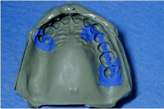
These are usually taken using alginate in a stock tray. For distal extension edentulous areas (Kennedy Class I and II), modify the tray first with compound or silicone putty.

3. Occlusal record

 If MIP (Maximal Intercuspal Position)  is obvious, the occlusion can be recorded conventionally at the same visit as first impressions. If MIP is not obvious, occlusal rims (wax record blocks) will be required, as will a separate visit. Where there are no teeth in occlusal contact, the steps involved are the same as for recording the occlusion for F/F (full upper and lower dentures) . If there is an occlusal stop but insufficient standing teeth to produce a stable relationship of the casts, the procedure is as follows:
  • Determine the VDO (Vertical Dimension Of Occlusion) and mark the position of two index teeth with pencil.
  • Define the arch form and occlusal plane using the occlusal rim on which this is easiest, e.g., tooth to tooth, tooth to retromolar pad.
  • Check the occlusal rim in the mouth, using the mark on the index teeth as a guide, and adjust blocks if necessary.
  • Record occlusion with bite-recording paste or wax.
  • Check that the relationship of the index teeth on the articulated casts corresponds to that in the mouth.
4. Survey mounted casts and design denture


Surveying
A dental surveyor should be used to determine heights of contour with a common path of insertion.
Objectives
  • Establish path of insertion.
  • Define those undercuts that may be used to retain denture.
  • Define those undercuts that require blocking out prior to finish.
If the path of insertion is at 90° to the occlusal plane insertion of the denture will be straightforward; however, where the teeth are tilted or few undercuts exist, an angulated path of insertion may be advantageous. Which path provides more resistance to displacement during function is controversial.
A survey line can then be marked on the teeth to indicate their height of contour in the plane of the path of withdrawal.

5. Tooth preparation may be required to:
  • Accommodate rest seats. Rests need to be >1 mm for strength, if insufficient room in occlusion to accommodate this bulk, tooth reduction is required.
  • Establish guide planes
  • Modify unfavorable survey line, e.g., ↓ height of contour
6. Final impressions using a custom tray.

Alginate is the most commonly used material, but elastomers are preferable for deep undercuts. It is helpful to have a wax try-in before the framework is made. This enables you to confirm tooth position so that the retentive elements for the acrylic are placed appropriately.

7. Framework try-in

  • Check extension, adaptation, and position of clasp, and rests. If casting does not fit, use of correcting fluid or a fit checking material (e.g., Fit-Checker) may reveal which areas to relieve.
  • Check upper and lower separately for VDO and occlusion, and then together.
  • Major faults: repeat final impressions.
  • Minor faults: adjust at finish.
  • Make new occlusal record, if required.
  • Select tooth mold and shade.
  • Use altered cast technique, if required.
8. Wax try-in

  • Check position of denture teeth.
  • Check flange extensions/thickness.
  • Check VDO, arch form, occlusal plane and occlusion.
  • Check aesthetics with patient and only proceed when patient is satisfied.
  • Prescribe post-dam relief areas and management of undercuts.
9. Finish once any fitting surface roughness is eliminated, the dentures are tried in separately, adjusting undercuts and contacts as required. The extension, occlusion, and articulation are then adjusted if necessary. Give the patient written and verbal instructions, and a further appointment.

Friday, October 21, 2011

A Note onExamination of the occlusion


Introduction
As stated in the previous section, the principle function of the concept of ideal occlusion in everyday dentistry is to provide a benchmark against which any patient’s occlusal pattern can compared. This does not infer that the provision of an ideal occlusion is the treatment objective for that particular patient nor for patients in general.
The three question examination
Question 1.
Does Centric Occlusion occur in Centric Relation?
Centric relation describes a relationship between the two jaws, it has nothing to do with teeth; it is not an occlusion. When the head of the condyle is moving purely in the rotational phase of its movement, then the mandible is in a terminal hinge axis. This concept provides one of the three pillars of the definition of centric relation that is given in the previous section. If the head of the condyle is the stationary centre about which the mandible is rotating, then the mandible, during this phase of movement will describe an arc. Whereas if the mandible is not in terminal hinge axis, then the head of the condyle will not be purely rotating, because there will be an element of translation; and as a consequence of the fact that the head of the condyle is, therefore, not stationary (in the antero-posterior plane)  the mandible will not describe an arc.
Manipulation of patient to find the Centric Relation
 It is feeling that the patient’s mandible is describing a perfect arc during manipulation that gives the experienced operator the confidence that the terminal hinge axis of the mandible  has been found.
 Illustration of the relationship between the condyles 
It is certain that in reality the mandible is not describing a perfect arc because unlike on an articulator the condyle is never a perfect sphere and the glenoid fossa is never a hemisphere. There is, however, one important test that provides confidence that Centric Relation has been found. This test is based upon the fact that because the Centric Relation is a jaw relation-ship not guided by teeth nor by the patient’s muscles but by the operator arcing the mandible in its terminal hinge axis towards the maxilla, and that the end point of this arc will be consistent.  The end point of this arc occurs when the first teeth touch and this is known as the premature contact in the Centric Relation. Centric Relation is the only ‘Centric’ which is consistent. It is the fact that the Centric Relation has been found to be consistent in any one patient irrespective of time or operator that makes it so significant as a concept. It may be that the end point of the closing arc of the mandible whilst it is in terminal hinge axis (Centric Relation) is not a premature contact but rather an even contact of all of the teeth (Maximum Intercuspation). In this case the Centric Relation and Centric Occlusion coincide. If, however, as is usually the case this ideal situation does not occur then the Centric Occlusion will not occur in Centric Relation. It will then be possible discover where the premature contact in Centric Relation is.
How to find the Centric Relation
The positional difference between Centric Relation and Centric Occlusion can further be examined by noting the direction of slide of the mandible when the patient is asked to clench his or her teeth together whilst resting on the Centric Relation premature contact.
If Centric Relation (CR) and Centric Occlusion(CO) do not coincide, in many ways it would make more sense to describe the relationship between the jaws when the teeth are in Centric Occlusion, and not the other way round; but that is impossible to do because there are no landmarks on the jaws that can be examined whilst the patient is holding his or her teeth in Centric Occlusion. So the question has to be: ‘ Does CO occur in CR?’.
Question 2.
Does the patient have Freedom in Centric Occlusion?
This investigation will answer the question: ‘Is the patient’s Centric Occlusion locked in?
This means when the patient is biting together normally, do his or her incisor teeth prevent those teeth moving slightly forward, or are they prevented from doing so (locked), by the fact that the lower incisor teeth heavily contact the palatal surfaces of the upper incisor teeth?
It can be examined by in one of three ways:
1. Marking the occlusal contacts and seeing if the anterior contacts are heavier than the posterior ones
2. Asking the patient to close together slowly and reporting which teeth hit first
3. Feeling for tremors on the upper incisor teeth with our finger nail whilst the patient repeatedly taps up into Centric Occlusion.
This was easier in the days before routine use of gloves.
Question 3.
Where is the patient’s Anterior Guidance?
It  has already been discussed that the term ‘anterior guidance’ should not be taken to mean the guidance that is on the front teeth: it is the mandible that is being guided, by the temporo-mandibular joints (posterior guidance) and by the teeth (anterior guidance). Therefore, which ever teeth touch during excursive movements of the mandible provide the anterior guidance or the dynamic occlusion.
However,  the benchmarch against which the patient’s occlusion is measured is ideal occlusion, and in an occlusion which is ideal for the rest of the articulatory system the anterior guidance is on the front teeth.
How to examine anterior guidance
When the anterior guidance is on the back teeth the terminology used is posterior interference. This may be either on the working or non-working side. If interferences are present then they may extend beyond the crossover position. If there are no posterior interferences, then the anterior guidance will be on the front teeth, and this is described as being either ‘canine guidance’ (where the contact between the upper and lower teeth during an excursive movement of the mandible is against the upper canine and then eventually on the upper central incisors); or it is described as a ‘group function’ where the anterior guidance is on several teeth. In a group function these contacting teeth are usually the canines and first and second pre-molars; the more anterior teeth of the group should provide the earlier and harder contacts, otherwise the contact could be considered as a working side interference.

A Video on Mandibular movement

Tuesday, October 11, 2011

DENTURE FRACTURE & REPAIR LECTURE NOTE


DENTURE FRACTURE & REPAIR
Technically Dentures can fracture in one of two ways:
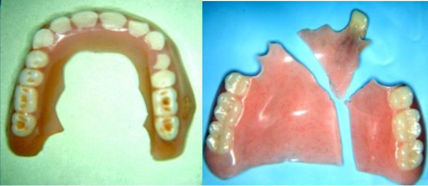
   By  IMPACT  where one hard blow results in instant breakage
   By  FATIGUE  when the denture base is subjected to repeated stresses.


IMPACT FRACTURE
An impact fracture is usually caused by patient carelessness or accident.
Impact fracture
FATIGUE FRACTURES
May be associated with 
(1) The design of the denture
(2) Oral anatomy of the patient.
(3) Its use or abuse by the patient.
(4) Factors introduced in the laboratory.
(5) Previous repairs.

A "U" shaped denture  designed
A large diastema between the anterior teeth
This denture has become bleached and very thin with long-term cleaning and wear.
Non-flanged or “open-faced” denture
As a result of prolonged use of abrasive cleaners and vigorous brushing over many years acrylic resin will wear very thin and therefore become very prone to fatigue.
Upper denture with a high vaulted palate
PPT Note on Denture Fracture & Repair


Download PDF Lecture Note

Sunday, September 25, 2011

A Short Note On Overdentures....with ppt for download.


Overdenture
A complete or partial removable denture supported by retained roots that is intended to provide improved support, stability, and tactile and proprioceptive sensation and to reduce ridge resorption.

    Advantages
  Preserve alveolar ridge
  Possibly
                -support
                -proprioreception
                -retention (eventually)
                -stress distribution
       Disadvantages
·                      Poor oral hygiene
                             -caries and periodontal disease
  Soft tissue undercuts
                -esthetics
                -retention
  Breakage of denture
                -thin
                -stress concentration over abutments

Selection of abutment teeth
  One per quadrant
  Not adjacent teeth
  Usually mandibular cuspids and premolars
  Maxillary cuspids frequently cause esthetic and retention problems due to soft tissue undercuts

Overdentures
  Regard as transitional
                        - need perfect oral hygiene
                        -daily non acidulated topical fluoride (sodium fluoride)
  Probably better to place 2 implants
A Video On Implant Supported Overdenture

Saturday, September 24, 2011

OSSEOINTEGRATION IN IMMEDIATE LOADED DENTAL IMPLANTS

IMMEDIATE LOADED DENTAL IMPLANTS


Advantages of immediate placement
1  Implants    in  fresh    extraction    sites    can be  placed    in  the  same    position  as    the extracted  tooth,    minimizing  the  need  for angled abutments.
2 Osseointegration   is   more   favorable   when implants   are   placed   immediate   following an extraction.
3 The  bony  receptors  are  preserved  by preventing   atrophy  of   the   alveolar   ridge,  preventing   recession  of   the   mucosal   and gingival   tissues.   Reports   indicate   that   a significant  amount  of  crestal  bone  is  lost by delaying the load on implants.
4 Non-functional    restorations    can    be   provided    for  better  esthetics,    especially    in the anterior region.
5 lmmediate placement of implants keeps contaminants away from the socket.
6 Waiting  times  for  primary  healing  of the   soft   tissues   and   regeneration   of   the   osseous structure are eliminated.
7 More   patients   will   opt  for  implant   treatment  (no  waiting  for  healing,    immediate restoration


 A Video Of Dental Implant Procedure

Wednesday, September 21, 2011

A Note ON Immediate Dentures......With ppt Download

Immediate Dentures
An immediate denture is “a complete denture or removable partial denture fabricated for placement immediately after the removal of natural teeth”
Types
Conventional immediate denture:
the denture is intended to be  relined to serve as the long-term prosthesis.
Interim (or transitional) immediate denture (IID):
after healing is completed, a second, new complete denture is to be fabricated as the long-term prosthesis.
Advantages

  • Maintenance of a patient's appearance
  •     Circumoral support, muscle tone, vertical dimension of occlusion, jaw relationship, and face height can be   maintained. The tongue will not spread out as a result of tooth loss
  •     Less postoperative pain is likely to be encountered because the extraction sites are protected
  •     Easier to duplicate (if desired) the natural tooth shape and position
  •     Adaptation easier. Speech and mastication are rarely compromised, and nutrition can be maintained
Disadvantages

    • Immediate dentures are a more challenging
    • The anterior ridge undercut that is caused by the presence of the remaining teeth may interfere with the impression procedures
    • The presence of different numbers of remaining teeth in various locations frequently leads to recording  incorrectly the centric relation position
    • No denture tooth try-in in precludes knowing what the denture will actually look like on the day of insertion
    • More chair time, additional appointments, and therefore increased costs

A Lecture Note On Immediate Dentures

Monday, September 19, 2011

Rationale Behind Axial Positioning Of Implants

Axial Positioning Rationale
Implant positioning in relation to its axial level influences the amount of exposure the final restoration will receive, which in turn dramatically affects the esthetic outcome of the restoration (Jansen and Weisgold 1995). Apico-incisal positioning is no less important than the mesiodistal and labiopalatal positioning aspects of the implant. Unfortunately, surgical templates that offer apicoincisal positioning guidance for functional or esthetic implant placement are few. They are often difficult to fabricate and they are not cost effective. Most of the recent computer-generated templates have a metallic stop to control the apical extent of the drill. The optimal axial positioning of the implant head allows the final restoration to emerge naturally through the marginal gingival tissues with no violation to the gingival sulcus (Wheeler 1974), allowing the contours of the restoration to develop in a progressive manner within the peri-implant soft tissue housing. As a result, the final prosthetic result appears as if it emerges naturally.
Several factors control the location of the implant head in an axial dimension, including
  (1) the amount of space available for restoration,
  (2) the topography of the remaining bone,
  (3) the marginal gingival location of the adjacent natural teeth, and
  (4) the selected implant diameter.
The optimal axial location of the implant head is necessary due to the anatomical difference between the fixture morphology and that of the natural tooth at the cervical level. A morphological transition from the narrow circular implant neck from the implant head to that of the natural tooth form is naturally required.
The reference location of all axial implant positioning is an imaginary line connecting the gingival zeniths of the adjacent natural teeth. There is a greater urgency for restoring natural gingival contours surrounding the new restorations when a natural tooth reference is missing and multiple adjacent implants are to be used. These implants should be placed at the alveolar crest within the circumference of the missing teeth to be restored. This enables the clinician to develop appropriate natural embrasures on both sides adjoining the restorations and duplicate a natural gingival profile (Potashnick 1998). The ideal apico-incisal implant positioning places the implant head 2 mm to 3 mm apical to the line connecting the gingival zeniths of the adjacent natural teeth. This subsequently allows “running room” throughout the biological width of the implant when it is correctly positioned in an apicoincisal plane (Parel and Sullivan 1989), as shown in figure.
An illustration showing the ideal axial positioning of the implant, 2–3 mm from the line connecting the gingival zenith of the natural teeth.

The “running room” is a space of 2 mm to 3 mm in depth and it surrounds the implant head circum-ferentially, as shown in Figure.
The ideal distance from the gingival zenith to the implant head. The blue line represents the gingival zenith, and the green line represents the optimal implant axial position.

This room allows for stacking or building up of prosthetic components to create the natural gingival emergence of the final restoration. If any modification or expansion of the gingival tissues to match the original crown size takes place in this particular space, the progressive use of the pro-visional restoration will develop the original crosssectional shape of the missing natural tooth. The use of anatomical abutments has not proven to be more effective than the progressive use of the provisional restoration. Because the gingival tissue does not have a memory to keep its original dimensions without existing support, the peri-implant soft tissue tends to collapse and regain its original circular shape (due to the pressure from the circular collagen fibers surrounding the biological seal) upon its removal from the gingival sulcus. Clinically speaking, natural biological contours could be replicated without the need for anatomical abutments. Provisional prostheses have proven to give an optimal gingival influence with great clinical predictability.
An illustration showing the difference in cross section between implant and natural tooth and the running room.

Implant diameter has an inverse relationship to the amount of subgingival sinking. It influences the amount of axial sinking of the implant head, because implants with wide diameters eventually require less space for making the transition into a natural tooth form than narrow-diameter implants. Bear in mind that not all the biological concepts are violated. The screw design implant ranks first to allow a more precise axial placement than the cylindrical designs. Its mechanical characters allow control of the depth while threading the fixture in the bone. The cylinder design, on the other hand, requires the use of an implant retrieval tool to adjust the implant’s optimal vertical position, which makes the procedure difficult to control.
An illustration showing that wider implants require less apical positioning.

Gingival zenith of the adjacent natural teeth is considered to be the landmark or the reference in apico-incisal implant positioning. Therefore, for a number of reasons, it is recommended that the location of the implant head be related to a line connecting the gingival zenith of the adjacent remaining natural dentition rather than to a line connecting the CEJ or the crest of the ridge. For instance, the gingival zenith is not a static landmark; it sometimes moves apically, such as in the case of gingival recession, because it represents the actual clinical marginal level of the soft tissue at the time of implant placement. In contrast, the CEJ is a constantly static landmark. It follows a uniformly fixed scalloped path along the root surface. It also pursues a wavy course that has a rise and fall on both buccolingual and interproximal margins. This scalloped line does not move when gingival recession occurs, thus it does not allow for optimal apicoincisal positioning in the case of gingival recession and in cases of placing an implant in unbalanced soft tissue margins.
Two unsymmetrical gingival margins: the blue line represents the actual gingival zenith, the red line represents the CEJ, and the green lines show the calculation of the distance form the deepest point of the gingival zenith to the implant head represented in the black line.

Also, the wavy course of the CEJ does not give a table reference with which to measure. The use of the deepest part of the gingival zenith allows the final implant-supported restoration to attain the same marginal level as those existing around natural dentition, as shown in following figure.
In the case of gingival recession, it is impossible to relate the axial positioning to the CEJ. The red line represents the CEJ, the blue line represents the actual gingival marginal position, and the green line represents the osseous crest levels.

The crest of the ridge is a less than ideal reference point for making a measurement to relate the implant head because the nature of bone resorption sometimes makes it variable in its levels. In other words, in many instances the osseous housing is not the optimal land-mark. Soft tissue thickness on top of it can be variable as well, which might lead to unpredictable variable measurements, as shown in following figure.
In cases of vertical bone resorption, the implant head can be located over the osseous crest, which proves the fact that the implant head should be related to the line connecting the gingival zenith. The green line represents that osseous crest, the black line represents the implant head level, and the blue line represents the gingival zeniths.

For example, when the alveolar ridge has undergone a process of vertical osseous resorption, the implant head will eventually be situated above the bone level. Therefore, the osseous crest should not be taken as a reference measuring point.
An illustration showing the three different positioning possibilities.

Implant Guidelines for the Restorative Dentist lecture.....ppt

Share

+1 this blog

you might also like

Related Posts Plugin for WordPress, Blogger...